|
|
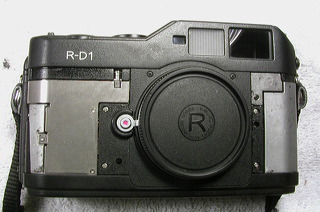
Here's the camera body with both front rubber grips removed (and the heavy adhesive residue cleaned off.) The right-side grip doesn't need to be removed fully to take off the top cover, but the left-side grip has to come off to allow removal of the silver plate at left. This plate covers two ribbon cables that have to be unplugged to remove the top cover. |
|
|
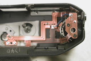
Most of the controls stay with the top cover; the only ones that need to be removed are the shutter button/speed dial assembly and the winding lever. This photo shows the inside of the top cover; this is the bottom of the jog dial, which can stay attached to the top cover and does not need to be removed. |
|
|
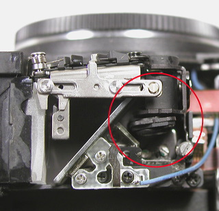
What makes the rangefinder work is a swinging lens (circled) behind the small secondary-image window. As the camera lens moves in and out for focusing, this lens swings from side to side. The swinging lens is shown here at the closest-focus position. |
|
|
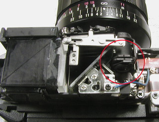
Here the swinging lens is shown in its infinity-focus position. Note the notches on the top of the swinging lens' frame and the frame of the fixed lens in front of it. These notches line up when the swinging lens is at its infinity position. |
|
|
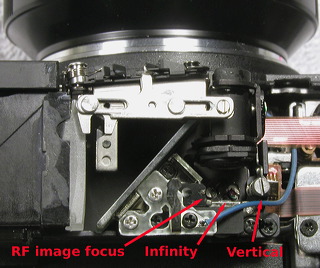
These screws adjust the position of the moving rangefinder image by shifting the swinging lens's frame. The leftmost screw moves the swinging lens to and fro (up and down in the picture) to focus the moving image for a clear view. The center screw moves the swinging lens left or right to line up the rangefinder image at infinity.
If you look carefully, you can see that these two screws are eccentrics: Their shafts are off-center and ride in slots. This means that if you turn one of these screws through one full turn, the swinging lens frame will move as far as it can go in one direction, then reverse itself and move back the other way. Why this is important: You can't count on, say, a clockwise turn ALWAYS moving the RF image in the same direction - once the eccentric reaches its limit, it will reverse direction.
The large gray vertical adjustment screw at right works differently and is shown more clearly in the next picture. |
|
|
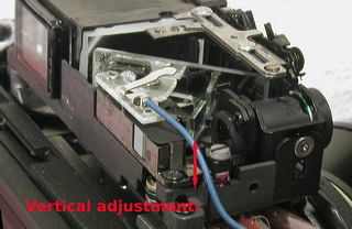
This shows the vertical adjustment screw. Turning it moves the black collar just below its slotted head; this collar is part of the moving lens frame. As the screw turns, the collar moves up and down to align the rangefinder image vertically.
NOTE: All three adjustments interact to each other to some extent, partly because of the geometry of the adjusting slots and partly because all the components are REALLY tiny -- a very small movement makes a big difference. |
|
|
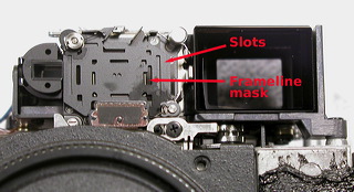
This front view shows how the frameline selection system works. The framelines are thin lines cut into a mask. A slotted plate fits over the mask; it moves so the slots uncover only the lines for the framelines you want to use. This whole assembly fits behind the front panel's frosted window, which provides diffused illumination that passes through the frameline mask and is reflected into the finder.
The small circuit board at the bottom of the mask is the shutter speed readout. |
|
|
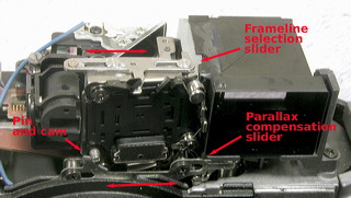
This view shows the frameline selector and parallax compensation linkage.
The slotted slider at the top connects to the frameline selecting lever on the top cover. When you change the lever, a pin on its inside end slides the slider back and forth. A projection on its front end hits the two black diagonal "fingers" visible at the top of the frameline mask; these fingers move the correct set of slots into place.
The parallax compensation slider also moves from side to side. It's controlled by a linkage to the camera's focus coupling arm; this linkage is underneath the rangefinder module. As the slider moves from side to side, a slanted cam on its left end presses against a pin that's connected to the frameline mask assembly. The action of the cam against the pin moves the entire mask assembly diagonally, compensating for parallax. |