CameraQuest Home Camera Articles FOR SALE Orders I Buy / Wants Repairs Books Adapters
Epson R-D1: Top plate removal
Procedure
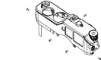
Removing the Epson R-D1 top plate is straightforward, so long as you prepare well and keep track of the order and placement of the various camera components during disassembly: no ball bearings or springs will ping out, never to be found! Figure 1 shows the components that you will need to remove in order to take off the top plate. Figure 2 shows the camera after removal of the top plate.
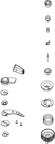 |
Figure 1. The Epson R-D1 components that need to be removed in order to take off the top plate. |
1. Tools: use decent jeweller’s screwdrivers (cross-point and flat blade required) – some of the screws are very tight. A spanner wrench is needed to disassemble the shutter button assembly; however, I used a cheap pair of tweezers instead, filed to shape – this home-made tool proved perfectly adequate.
2. Buy some double-side tape (for the rubber grip). Most types of double-sided tape are too weedy as you need strong adhesive: 3M Scotch Clear Heavy-Duty Mounting Tape is very good. (Note: you might want to take this opportunity to replace the rubber covering with real leather from Camera Leather.)
3. Remove the two screws from the bottom of the winder lever handle, then lift off the plastic and metal cover.
4. Slide the keeper off from the top of the winder arm shaft, and remove the tensioning washer and winder arm.
5. There’s a barrel shaped ketch on the shaft below the winder arm, it looks like a bushing with notches on each side: lift this off of the shaft. Note: arrange these small parts in the order they come off or take photos as you go, so you can reassemble it correctly.
6. Set the shutter speed dial to AE and ISO 200 (this will help when you put it back together).
7. Remove the collar nut around the shutter button. The button has a spring below it so release the nut slowly. Remove the collar nut, the shutter button, spring and shutter button keeper (the keeper looks like a washer with two ears – it keeps the shutter button from turning when you screw accessories into the top of the button).
8. Remove the shutter push rod, noting the direction it goes in (the collar on the push rod goes up). There’s a small push rod spring in the shaft below the push rod but mine stayed in place so I did not have to deal with it.
9. With the shutter button out of the way you’ll see another collar nut. This one may require a pin spanner to remove (I just pushed on the edge of the pin hole and it came loose). After you get this loose, lift off the dial.
10. Next, facing the front of the camera, remove the left-side rubber grip (it has double-sided tape holding it on).
11. Under the grip is a metal plate held in place with 3 small screws: remove the screws and plate.
12. Now, remove the two upper ribbon cables: the left one pulls straight out of the connector (no keeper); the right one is behind another ribbon cable and does have keepers. The keepers for this cable are on the sides of the connector (they’re brown): push straight up on the keepers, work side to side as required (they move up about 1 mm). Now you can lift the ribbon cable out of the connector.
Warning: be careful not to bend the ribbon cables sharply or overstress them, in case you break the copper tracks. They're not especially fragile, but don't, for example, subject the cables to the weight of the top plate dangling off them! If a track breaks, you can repair it by soldering copper wire across the break. Note: (a) if more than one track is broken, remove the lacquer from either side of the break on one track, and repair that break, then repeat for the next break – removing the lacquer from all tracks before soldering makes it likely that adjacent tracks will be soldered together (making an awkward job even more tedious); (b) remember to insulate the copper wire used for bridging.
13. Set the frame line switch to 50 (or whatever – just remember which setting it was on).
14. The last step is to remove the 5 black top plate retaining screws. There’s one above the display on the back of the camera, one on each side of the camera (you already have the left side grip off so you’ll see the left side screw). The right side screw is behind the right grip, you don’t have to remove the grip: just pull it loose in the upper side corner. Also, pull the right side grip loose along the top edge as it my be stuck to the top plate. The other two screws are on either side of the lens mount.
15. You should now be able to lift the top plate off.
This all sounds a bit complicated but once you know how this all works the top plate can be removed in 5 minutes.
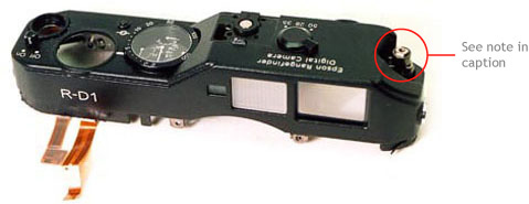
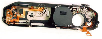
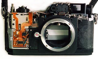
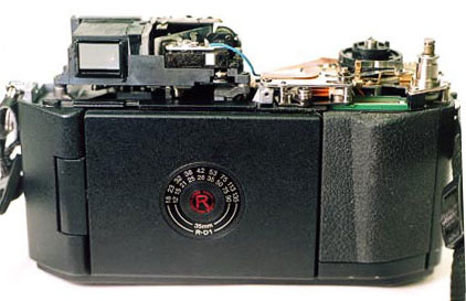
Figure 2. The Epson R-D1 after removal of the top plate. Note: the top image shows that the jog dial knob has been removed; this is not necessary – leave it on. (Photos: courtesy of Don Goldberg, DAG Camera Parts.)
Top plate replacement
There are a few things to note when replacing the top plate:
1. There’s a small bushing behind the right-hand screw above the lens mount. It’s attached to the top plate and can’t come off, but it is loose and may move out of position. If the top top plate won’t drop on completely, the cause is probably this bushing.
2. If you knock the camera when the top plate is off, the ISO mechanism on the camera can slip, so that the brass tab on the bottom of the knurled shutter-speed/ISO ring that you removed earlier will not locate correctly when replaced.
Solution. If you look down at the ISO mechanism on the camera, you will see a plate through the slots on top of the mechanism – if the brass locating tab won’t locate correctly, this plate has moved (it can rotate freely). Gently push it round until a rectangular hole is directly under where the brass tab will locate (to the rear of the camera if the ISO was set to 200 before dismantling the shutter-speed/ISO dial assembly).
3. The frame line switch should be in the same position as when you took it off. It fits into a slot to drive the frame line linkage, so when you have the top plate back on, just make sure the frame lines work before you screw down the top plate.
4. Some of the double-sided tape holding on the rubber covering may need to be replaced. Do not use cheap carpet tape or similar as it will come unstuck: instead, use something stronger, e.g. 3M Scotch Clear Heavy-Duty Mounting Tape.
5. When putting the rubber covering back on, stick it down lightly in position, then heat it with a hand-held hair dryer. This softens the covering (and adhesive) and makes it more flexible, allowing it to be pressed inwards along its edges, ensuring a close, flush fit. When the covering cools off, it will be fit tightly and stay put.
 Top plate removal